
Demo 7.2: The Arduino, and What a Program Actually Does
Every circuit in this module so far has done what it does because of how it is wired.
A gate inverts because of how its transistors are arranged. A counter counts because of which output goes to which clock input. Change the behaviour and you change the wiring, which is why the ripple counter needed a different connection to count down, and why the seven-segment decoder needed a different set of gates for a different set of patterns.
A microcontroller breaks that link. The wiring stays where it is and the behaviour becomes a list of instructions stored in memory, so the same board on the same breadboard is a counter this afternoon and a light meter tomorrow.
That is a genuine trade rather than an upgrade, and it is worth being clear about both sides of it before writing a line of code.
What is actually on the board
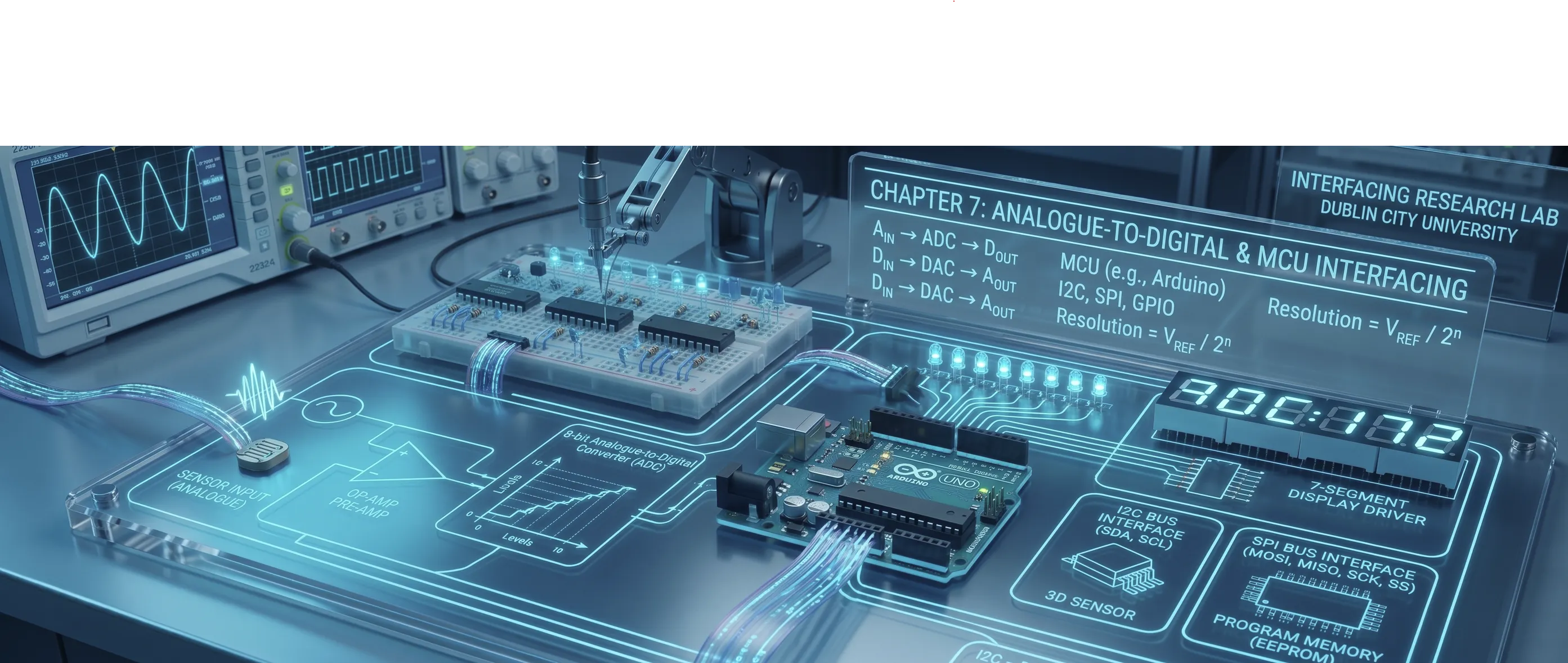
Section titled “What is actually on the board”An Arduino Uno is one chip with a few useful things around it. The chip contains a processor, some memory, a set of pins it can drive or read, and, importantly for this module, an analogue to digital converter and hardware that can switch pins on and off at a fixed rate.
Those last two are the whole of the previous demonstration, made concrete. analogRead is the converter. analogWrite is the switching hardware, and despite the name it is not a converter at all.
Two functions, and only two
Section titled “Two functions, and only two”Almost everything about how an Arduino program behaves follows from one fact: there is no operating system underneath it. Nothing else is running. The entire arrangement the board executes is
setup(), once, when the board powers up or is reset, andloop(), over and over, endlessly, until the power is removed.
There is no scheduler, no background, no other program waiting for a turn. Which is why the single most common source of confusion, delay(), behaves the way it does. It does not schedule anything and it does not run in the background, because there is no background. It stops.
The Arduino: setup(), loop() and the Pins
Two functions and nothing else running, what a pin actually is, the converter behind the analogue inputs, the duty cycle that is not a converter, and a display driven by seven wires and a table.
How to use it
Section titled “How to use it”Each tab asks a different question about the same board. The first two are about how a program runs and what a pin is; the middle two are the two crossings from the previous demonstration, done in code; the last one rebuilds a circuit you have already built in hardware.
Walkthrough
Section titled “Walkthrough”Step 1: Watch a program run
Section titled “Step 1: Watch a program run”Open setup() and loop(), choose Blink and press play.
The highlighted line is the one executing, and the panel beside it is a real timeline rather than an animation made to look plausible: every statement has the duration that operation genuinely takes, and the position in the program is worked out from a virtual clock.
Slow the speed right down and watch digitalWrite go past. It takes about 4 µs, which is why you have to hunt for it. Then watch delay(500) and notice that the highlight sits on that one line, doing nothing whatsoever, for half a second.
Look at the readouts:
One trip round loop() | 1000 ms |
| Of which is real work | 0.008 ms |
So loop() runs | 1 time a second |
Less than one part in a hundred thousand of that program is doing anything. Everything else is stopping.
Switch to Twice as fast to see the obvious change, and then to Without any delay. Same LED, same two flashes a second, but nothing blocks, so the loop now completes in about 4 µs and runs a quarter of a million times a second. Most of those trips do nothing except look at the clock and carry on.
Finally, choose Read and print, which is the loop the light-meter laboratory is built from. The conversion takes 0.104 ms, handing the text to the serial buffer takes about 0.1 ms, and then the program stops for 200 ms. Real work: about 0.2 ms out of every 200. That is normal, and it is completely wasted if anything else needed attention.
Step 2: Find out what a pin actually is
Section titled “Step 2: Find out what a pin actually is”Open The pins.
A pin is four things at once, and every one of them has caught somebody out:
- a direction, which you choose with
pinMode - a level, 0 V or 5 V, which you set or read
- a threshold, so that an input voltage becomes a
HIGHor aLOW - a current limit, which is small
Select OUTPUT first. The pin is now a small voltage source; driven HIGH it sits near 5 V, and through the 220 Ω resistor that gives 13.6 mA into the LED. That is the calculation from the diode and pull-resistor demonstrations, arriving unchanged.
The number worth memorising is 20 mA recommended per pin, 40 mA absolute, plus a further limit on all the pins added together. So one LED is fine, several want checking, and anything that moves needs a transistor between the pin and the load, which is exactly the conclusion the transistor demonstration reached about a logic gate output, for the same reason. A control output is not a power supply.
Now select INPUT and hold the button down. The pin is connected to 5 V and reads HIGH, and there is nothing wrong with that half of the circuit. Let go.
The reading starts changing on its own.
That is not a flaw in the demonstration. Nothing is connected to the pin at all, so it is floating, following whatever charge happens to be nearby. Move a hand near the board and it changes. It is the identical fault the pull-up and pull-down demonstration is about, arriving on a microcontroller instead of a 74HC part, and behaving identically because it is the same kind of input.
Then select INPUT_PULLUP. One word, and the chip connects a resistor of roughly 20–50 kΩ from the pin to 5 V. The pin now sits HIGH whenever nothing else drives it, and the button only has to pull it down.
Step 3: Read the world
Section titled “Step 3: Read the world”Open Reading the world, which puts the light sensor from the previous demonstration on pin A0.
Drag the light and watch the whole chain: resistance, then the divider’s voltage, then analogRead returning 0 to 1023. Multiply the reading back by 4.88 mV and you get the voltage it came from, which is worth doing once to convince yourself the number means something specific.
Two things to take from this tab.
The first is that the reading is a voltage, not a light level. Turning it into lux would need the sensor’s curve, and that curve is neither linear nor the same from one part to the next. For deciding bright from dark, or for driving a display, the raw number is entirely sufficient.
The second is the serial monitor at the bottom. A microcontroller has no screen and no error messages, so printing is the only way to find out what a program is actually doing. Print the value you have just read, before you use it, because most surprises turn out to be a sensor stuck at 0 or 1023 because of a wiring fault, rather than the logic being wrong.
Notice too that the readings are not perfectly steady even with the light held still. The last bit or two is often reporting noise rather than signal, and averaging a handful of readings is the standard answer.
Step 4: Write something that is not quite analogue
Section titled “Step 4: Write something that is not quite analogue”Open Writing a duty cycle and run Fade up and down on pin 11.
analogWrite(11, 128) sets the pin HIGH for about half of every period, at 490 Hz, which averages 2.5 V. The pin itself is still only ever at 0 V or 5 V; the LED follows every edge and your eye does the averaging. This is the previous demonstration’s PWM tab with a line of code in front of it.
Now move the LED to pin 12 and run the fade again.
Nothing fades. The LED sits off through the first half of the sweep, jumps to fully on, and stays there. No error appears, no warning is printed, and the code has not changed.
Pin 12 has no PWM generator behind it. Only 3, 5, 6, 9, 10 and 11 do, and the board prints a tilde beside those six for exactly this reason. analogWrite on any other pin quietly treats anything above about half as HIGH.
Then switch to Follow the light, which joins the two halves: read A0 to get 0–1023, divide by four to get 0–255, subtract from 255 to invert it, and write it out. Four lines. The division is exact, since 1024 ÷ 4 = 256, and it still throws away three quarters of the distinctions the converter made, which is fine for an LED and would not be fine for a calculation.
Step 5: Build the same display twice
Section titled “Step 5: Build the same display twice”Open Seven segments, in software and let the count run.
Seven pins, 2 to 8, one per segment, and a table in memory saying which segments make which digit. Press a digit and watch the matching row of the table light up alongside the segments.
You have built this circuit before. In the seven-segment demonstration it was a decoder: four bits in, gates working out which segments to light, no code at all. Here the same truth table lives in memory instead of in gates.
| Hardware decoder | Seven pins and a table | |
|---|---|---|
| Code | none | a table and a loop |
| Speed | instant | fast enough |
| Wires | four in | seven out |
| Can display | the ten digits it was built for | anything, including letters |
| To change it | rewire or replace the chip | change one line |
Neither is the right answer in general. A digital watch uses the hardware version because it must run for years on a coin cell; a laboratory bench uses the software one because next week it will need to do something else.
Two things to try before you leave the tab. Watch the current: display an 8 and all seven segments are lit at once, drawing about 95 mA out of seven pins together. Each pin is individually fine and the chip has a limit on the total, so that is a number to check rather than assume.
Then take the speed slider below about 50 ms and watch the digits blur into one another. Nothing is failing: your eye is averaging them, exactly as it averages a PWM waveform. That same fact is what makes multiplexed displays work: light one digit at a time, very fast, and let the eye put them together.
Check your understanding
Section titled “Check your understanding”A program's loop() contains delay(1000) and a check of a button. Roughly how often can it notice the button?
A pin is set with pinMode(pin, INPUT) and a button connects it to 5 V when pressed. What does digitalRead return when the button is released?
analogWrite(12, 128) is called on an Arduino Uno. What happens?
Match each item to what it does
Which of these are true of an Arduino Uno? Select all that apply.
Wrap-up
Section titled “Wrap-up”Six things to take away.
- There are two functions and nothing underneath them.
setup()once,loop()for ever. Every surprise about timing follows from there being no scheduler and no background. delay()stops the whole program. It is harmless in a program that only blinks and fatal in one that also has to watch a button. Comparingmillis()against a remembered time does the same job without stopping.- A pin is a direction, a level, a threshold and a current limit. Set the direction deliberately, never leave an input floating, and remember that 20 mA is the working figure.
analogReadis the converter from the previous demonstration, giving 0–1023 and needing a divider in front of it to turn a resistance into a voltage.analogWriteis not a converter. It is a duty cycle, on six pins only, and the pin is at a rail at every instant.- The same job can be gates or code. The seven-segment truth table is identical either way; what changes is whether it is realised in silicon or stored in memory, and that trade, fixed and fast against flexible and programmable, is behind almost every design decision you will meet.
Which brings the module round to where it started. The first demonstrations were about writing numbers in a base and adding them up, the middle ones about gates, thresholds and the circuits that remember, and this last one is the same material with a processor placed on top of it.
Nothing here replaced the electronics. It sits on it, and every limit the electronics has is still there: the current a pin can give, the levels a threshold needs, the resolution a converter has. All of them now have to be respected in software as well as in wire.
© 2026 Derek Molloy, Dublin City University. All rights reserved.